Dual tone block. Powerful and high-quality homemade sound amplifier
In many modern audio systems, whether it is a music center, home theater or even a portable speaker for a telephone, there is an equalizer, or, in other words, a tone block. With it, you can adjust the frequency response of the signal, i.e. change the amount of high or low frequencies in the signal. Tone blocks exist active, built, most often, on microcircuits. They require power, but do not weaken the signal level. Another type of timbre blocks is passive, they slightly weaken the overall signal level, but they do not require power and do not introduce any additional distortions into the signal. That is why in high-quality sound equipment, most often, passive tone blocks are used. In this article, we will look at how to make a simple 2-way tone block. It can be combined with a homemade amplifier, or used as a separate device.
Tone Block Diagram

The circuit contains only passive elements (capacitors, resistors). Two variable resistors are used to adjust the level of high and low frequencies. It is desirable to use film capacitors, however, if there are none at hand, ceramic ones will also do. For each channel, you need to assemble one such circuit, and in order for the adjustment to be the same in both channels, use dual variable resistors. The printed circuit board posted in this article already contains this circuit in duplicate, i.e. It has an input for both left and right channels.

Download board:
(downloads: 742)
Making a tone block
The circuit does not contain active components, so it can be easily soldered by surface mounting directly on the terminals of variable resistors. If you wish, you can solder the circuit on the printed circuit board, as I did. A few photos of the process:


After assembly, you can check the operation of the circuit. A signal is applied to the input, for example, from a player, computer or phone, the output of the circuit is connected to the input of the amplifier. By rotating the variable resistors, you can adjust the level of low and high frequencies in the signal. Do not be surprised if the sound is “not very good” in extreme positions - a signal with completely attenuated low frequencies, or, conversely, overestimated ones, is unlikely to be pleasant to the ear. With the help of the tone block, you can compensate for the uneven frequency response of the amplifier or speakers, and choose the sound to your taste.
Case manufacturing
The finished tone block circuit must be placed in a shielded case, otherwise the background cannot be avoided. As a body, you can use an ordinary tin can. Bring the variable resistors out and put handles on them. Along the edges of the can, be sure to install jack 3.5 connectors for sound input and output.Subwoofer Low Pass Filter
A woofer system is usually bulky and expensive, and given that the human ear cannot detect stereo at low frequencies, it makes no sense to have two woofers - one for each stereo channel. Especially if the room where the stereo system will work is not very large.
In this case, you need to sum the signals of the stereo channels, and then select the low-frequency one from the received signal. Figure 1 shows a diagram of an active filter made on two operational amplifiers of the microcircuit TL062.
Stereo channel signals are fed to connector X1. Resistors R1 and R2, together with the inverted input of op-amp A1.1, create a mixer that forms a common mono signal from a stereo signal, op-amp A1.1 provides the necessary amplification (or attenuation) of the input signal. The signal level is regulated by a variable resistor R3, which is part of the OOS circuit A1.1. From the output of A1.1, the signal goes to the low-pass filter at A1.2. The frequency can be adjusted with a dual variable resistor consisting of R7 and R8.
The low-frequency signal to the low-frequency ULF or active low-frequency speakers comes through the X2 connector.
The power supply is bipolar, it comes through the X3 connector, it is possible from ± 5V to ± 15V. The circuit can be assembled on any two general-purpose operational amplifiers.
Mixer for working with three microphones.
If you need signals from three separate sources, such as microphones, to be fed into one input of an audio recording or playback device, you need a mixer with which you can combine the audio signals from three sources into one, and adjust their level ratio as required.

Figure 2 shows a mixer made on a chip like LM348, which has four operational amplifiers.
The signals from the microphones are fed, respectively, to connectors X1, X2 and X3. Further, on microphone preamplifiers on operational amplifiers A1.1, A 1.2 and A1.3. The gain of each op-amp depends on the parameters of its OOS circuit. This allows you to adjust the gain over a wide range by changing the resistances of the resistors R4, R10 and R17, respectively. Therefore, if one or more of the signal sources is not a microphone, but a device with a higher output voltage level of the AF, it will be possible to set the gain of the corresponding op-amp by selecting the resistance of the corresponding resistor. Moreover, the gain setting range is very large - from hundreds and thousands to one.
Amplified signals from three sources are fed to variable resistors R5, R11, R19, with which you can quickly adjust the ratio of signals in the overall signal, up to complete suppression of the signal from one or more sources.
Actually the mixer is made on the op-amp A1.4. The signals to its inverse input come from variable resistors through resistors R6, R12, R19.
The low-frequency signal to an external recording or amplifying device is supplied through the X5 connector.
The power supply is bipolar, it comes through the X4 connector, it is possible from + 5V to + 15V.
The circuit can be assembled on any four general purpose operational amplifiers.
Preamplifier with tone block.
Many radio amateurs build UMZCH based on UMZCH integrated circuits, usually designed for automotive audio equipment. Their main advantage is that quite high-quality UMZCH is obtained in the shortest possible time and with minimal labor costs. The only drawback is that the ULF is not complete, without a preamplifier with volume and tone controls.

Figure 3 shows a diagram of a simple preamplifier with a volume and tone control, built on the most common element base - transistors of the type KT3102E The amplifier has a large enough input impedance to handle almost any signal source, from a PC sound card and digital player, to an archaic turntable with a piezoelectric cartridge.
The cascade on the transistor VT1 is built according to the emitter follower circuit and serves mainly to increase the input resistance and reduce the influence of the output parameters of the signal source on the tone control.
The volume control - a variable resistor R3, is also the load of the emitter follower on the transistor VT1.
Next - a passive bridge tone control for low and high frequencies, made on variable resistors
R6 (low frequencies) and R10 (high frequencies). Adjustment range 12dB.
The cascade on the transistor VT2 serves to compensate for signal level losses in the passive tone control. The gain of the cascade on VT2 largely depends on the value of the OOS, specifically the resistance of the resistor R13 (the smaller, the greater the gain). The DC mode is set by the resistor R11 for the cascade on VT2 and R1 for the cascade on VT1.
The stereo version should consist of two such amplifiers. Resistors R6 and R10 must be dual in order to control the tone simultaneously in both channels. Volume controls can be made separate for each channel.
Supply voltage 12V, unipolar, corresponds to the nominal supply voltage of most microcircuits - integrated UMZCH, designed to work in automotive technology.
Radio adapter
All stationary audio equipment must have line-out and line-in connectors. You can apply a signal from an external source to the line input in order to use the main device as an amplifier with speakers or for recording. In most portable equipment, there is simply no line input. The only "means of communication with the outside world" are a microphone and a built-in radio receiver. A friend of mine tried to rewrite the signal from an MP-3 flash player onto a magnetic cassette by putting headphones on the microphone "hole" of an old portable CD radio. It turned out awful. Although, it was possible to use the built-in FM receiver, but this requires at least the simplest adapter.
For high-quality stereo signal transmission, you can use a purchased FM modulator designed for wireless connection of an external audio source to the car radio. It has a stereo modulator, a good transmitter with a frequency synthesizer, and often a built-in MP-3 player with an external flash drive or memory card. Well, in the simplest case, you can make a primitive single-transistor low-power transmitter, the signal of which the receiver can receive when the transmitter is close to its antenna.
The adapter diagram is shown in Figure 4.

The circuit is a cascade of an RF generator on a transistor VT1, operating in RF according to a common base circuit, in the base circuit of which a modulating low-frequency signal is supplied.
An audio frequency signal from an external source is fed to the VT1 base through a capacitor C4 and two resistors R1 and R2, serving as a stereo channel mixer. Since the circuit is very simple and there are no nodes in it that form a complex stereo signal, the receiver will receive a signal in monophonic form at the input of the receiver.
The low-frequency voltage, supplied to the base of the transistor VT1, changes not only its operating point, but also the junction capacitance. The result is mixed amplitude-frequency modulation. Amplitude modulation is effectively suppressed in the receiving path of the radio receiver, and frequency modulation is detected by its frequency detector.
The RF frequency at which the broadcast occurs is set by the L1-C2 circuit. In fact, there is no antenna - the adapter is located in close proximity to the receiver antenna, and the signal to it comes directly from the loop coil.
The loop coil L1 is frameless, its inner diameter is 10-12 mm, it is wound with PEV 1.06 wire, only 10 turns. You can tune the circuit both with a tuning capacitor, and by compressing and stretching the turns of the coil.
Power - two elements of 1.5V (3V).
Level indicator.
To properly establish a stereo balance and prevent overloading the ULF and acoustic systems, it is desirable that the ULF include an indicator of the level of the signal entering the ULF input.
From a practical point of view, for self-production, an indicator based on an LED scale is best, it is mechanically much stronger than a dial one and simpler and cheaper than a scale mnemonometric one.
Figure 5 shows the indicator circuit for both stereo channels. It is based on a microchip. TA7666R.
Inside the TA7666R IC there are two amplifiers with detectors at the outputs and two lines of comparators, five comparators for each channel.

The gain of each of the amplifiers can be set individually by selecting the resistance of resistors R1 and R2. With the value indicated in the diagram, the first stage of the LEDs (НL1 and HL6) lights up at input levels of 48 mV, the second stage (HL2, HL7) at 86 mV, the third stage (HL3, HL8) at 152 mV, the fourth stage (HL4, HL9) at 215 mV, the fifth (HL5, HL10) at 304 mV. The way the indication is displayed is “bar”, that is, the “thermometer column”, in other words, the larger the signal, the longer the line of luminous LEDs.
You can always change the sensitivity by selecting the resistances of resistors R1 and R2.
Based on this microcircuit, it is possible to make a kind of light-dynamic device, for example, made up of concentric circles of incandescent lamps or LED lamps, for example, used in automotive optics. In this case, additional powerful output stages are required.
Figure 6 shows a diagram of the output stage for driving automotive LED lamps. An optocoupler with a phototransistor U1 is used, its LED is connected instead of the indicator LED.
HF1 is an automotive LED bulb. It is powerful and a powerful key field-effect transistor VT1 is used for its switching.
Grinev V.A.
Recently, a certain person turned to him with a request to assemble an amplifier of sufficient power and separate amplification channels for low, medium and high frequencies. before that, I had already collected it for myself more than once as an experiment, and, I must say, the experiments were very successful. The sound quality of even inexpensive speakers of a not very high level is noticeably improved compared to, for example, the option of using passive filters in the speakers themselves. In addition, it becomes possible to quite easily change the crossover frequencies and the gain of each individual band and, thus, it is easier to achieve a uniform frequency response of the entire sound amplifying path. In the amplifier, ready-made circuits were used, which had previously been tested more than once in simpler designs.
Structural scheme
The figure below shows the diagram of 1 channel:

As you can see from the diagram, the amplifier has three inputs, one of which provides for a simple possibility of adding a preamplifier-corrector for a vinyl player (if necessary), an input switch, a preamplifier-timbral lock (also three-band, with adjustable HF / MF / LF levels), volume control, filter unit for three bands with adjustable gain level for each band with the ability to turn off filtering, and a power supply for high-power final amplifiers (unstabilized) and a stabilizer for the “low-voltage” part (preliminary amplification stages).
Pre-amplifier tone block
A scheme was used as it, which had been tested more than once before, which, with its simplicity and availability of parts, shows quite good characteristics. The scheme (like all subsequent ones) was once published in the Radio magazine and then published more than once on various sites on the Internet:
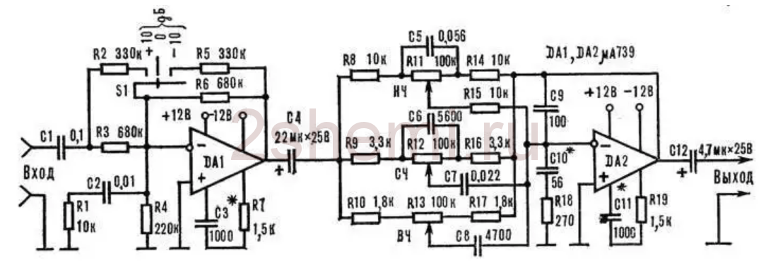
The input stage on DA1 contains a gain level switch (-10; 0; +10 dB), which simplifies the coordination of the entire amplifier with signal sources of different levels, and the tone control is directly assembled on DA2. The circuit is not capricious to some variation in the values of the elements and does not require any adjustment. As an op amp, you can use any microcircuits used in the audio paths of amplifiers, for example, here (and in subsequent circuits) I tried imported BA4558, TL072 and LM2904. Any one will do, but it is better, of course, to choose op-amp options with the lowest possible level of intrinsic noise and high speed (input voltage rise ratio). These parameters can be found in reference books (datasheets). Of course, it is not at all necessary to use this particular scheme here; it is quite possible, for example, to make not a three-band, but a regular (standard) two-band timbre block. But not a "passive" circuit, but with amplification-matching stages at the input and output on transistors or op-amps.
Filter block
Filter circuits, also, if desired, you can find a lot, since there are enough publications on the topic of multiband amplifiers now. To facilitate this task and just as an example, I will give here a few possible schemes found in various sources:

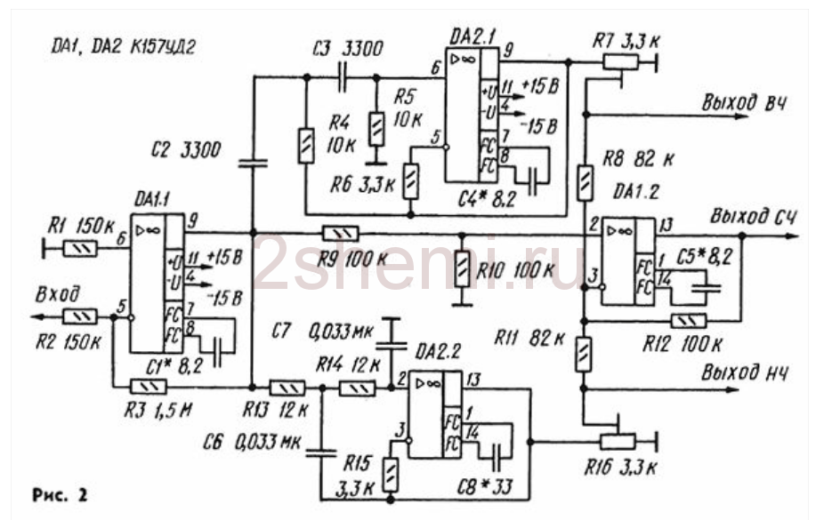
- the circuit that was used by me in this amplifier, since the crossover frequencies turned out to be just the ones that the “customer” needed - 500 Hz and 5 kHz, and nothing had to be recalculated.
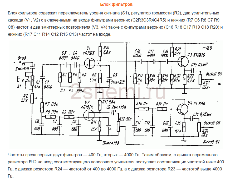
- the second scheme, simpler on the OS.
And another possible circuit, on transistors:
As yours already wrote, I chose the first scheme because of the rather high-quality band filtering and the compliance of the band separation frequencies with the given ones. Only at the outputs of each channel (band) were added simple gain level controls (as is done, for example, in the third circuit, on transistors). Regulators can be set from 30 to 100 kOhm. Operational amplifiers and transistors in all circuits can be replaced with modern imported ones (taking into account the pinout!) To obtain better circuit parameters. All these schemes do not require any adjustment, if it is not required to change the crossover frequencies. Unfortunately, I don’t have the opportunity to give information on the recalculation of these section frequencies, since the circuits were searched for “ready-made” examples and detailed descriptions were not attached to them.
In the filter block circuit (the first circuit of three), the ability to disable filtering for the midrange and high-frequency channels was added. For this, two push-button switches of the P2K type were installed, with which you can simply close the connection points of the filter inputs - R10C9 with their corresponding outputs - “high-frequency output” and “mid-range output”. In this case, the full sound signal goes through these channels.
Power Amplifiers
From the output of each filter channel, the HF-MF-LF signals are fed to the inputs of power amplifiers, which can also be assembled according to any of the known schemes, depending on the required power of the entire amplifier. I made UMZCH according to the scheme known for a long time from the Radio magazine, No. 3, 1991, p.51. Here I give a link to the "original source", since there are many opinions and disputes about this scheme about its "quality". The fact is that at first glance this is a class “B” amplifier circuit with the inevitable presence of “step” type distortions, but this is not so. The circuit uses current control of the output stage transistors, which allows you to get rid of these shortcomings with the usual, standard inclusion. At the same time, the circuit is very simple, not critical to the parts used, and even transistors do not require special preliminary selection in terms of parameters. In addition, the circuit is convenient in that powerful output transistors can be placed on one heat sink in pairs without insulating gaskets, since the collector leads are connected at the point " output", which greatly simplifies the installation of the amplifier:

When setting up, it is only IMPORTANT to choose the correct operating modes for the transistors of the final stage (by selecting resistors R7R8) - on the bases of these transistors in the “rest” mode and without load, the output (speaker) should have a voltage within 0.4-0.6 volts. The supply voltage for such amplifiers (there should be 6 of them, respectively) was raised to 32 volts with the replacement of the output transistors with 2SA1943 and 2SC5200, the resistance of the R10R12 resistors should also be increased to 1.5 kOhm (to "make life easier" for the zener diodes in the circuit power input op amps). The op amps were also replaced by the BA4558, and the “zero setting” circuit is no longer needed (outputs 2 and 6 in the diagram) and, accordingly, the pinout changes when soldering the microcircuit. As a result, when checking each amplifier according to this scheme, it gave out power up to 150 watts (for a short time) with a completely adequate degree of heating of the radiator.
ULF power supply
As a power supply, two transformers with rectifiers and filters were used according to the usual, standard scheme. To power the low-frequency band channels (left and right channels) - a 250-watt transformer, a rectifier on diode assemblies of the MBR2560 type or similar, and capacitors 40,000 microfarads x 50 volts in each power arm. For midrange and high-frequency channels - a 350-watt transformer (taken from a burned-out Yamaha receiver), a rectifier - a TS6P06G diode assembly and a filter - two capacitors of 25,000 microfarads x 63 volts for each power arm. All electrolytic filter capacitors are shunted with film capacitors with a capacity of 1 microfarad x 63 volts.
In general, the power supply can be with one transformer, of course, but with its corresponding power. The power of the amplifier as a whole in this case is determined solely by the capabilities of the power source. All preamplifiers (tone block, filters) are also powered from one of these transformers (it is possible from any of them), but through an additional bipolar stabilizer unit assembled on a Kren (or imported) MS or according to any of the typical transistor circuits.
The design of a homemade amplifier
This, perhaps, was the most difficult moment in manufacturing, since there was no suitable ready-made case and I had to invent possible options :-)) In order not to sculpt a bunch of separate radiators, I decided to use a radiator case from a car 4-channel amplifier, quite large, something like this:

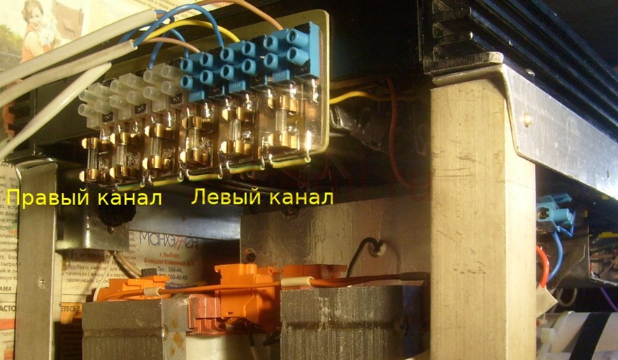
All the "insides" were, of course, extracted and the layout turned out to be something like this (unfortunately I did not take a corresponding photo):

- as you can see, six terminal UMZCH boards and a pre-amplifier-tone block board were installed in this radiator cover. The board of the filter block no longer fit, so it was fixed on the then added aluminum corner structure (it can be seen in the figures). Also, transformers, rectifiers and power supply filters were installed in this "framework".
The view (front) with all the switches and controls turned out like this:

Rear view, with speaker output blocks and fuse box (since no electronic protection circuits were made due to lack of space in the design and in order not to complicate the circuit):
In the future, the frame from the corner is supposed, of course, to be covered with decorative panels to give the product a more “tradeable” look, but this will be done by the “customer” himself, according to his personal taste. But in general, in terms of sound quality and power, the design turned out to be quite decent. Material author: Andrey Baryshev (especially for the site website).
Tone block with microphone amplifier for stereo power amplifier
The timbre block can be used as a component of a stereo amplifier or to refine an existing amplifier design. In addition to the line input for connecting an external signal source: radio, telephone, MP3 player, CD and DVD players, etc. There is a microphone amplifier on the tone block board. To connect a microphone, the board has a 6.3 mm jack socket. Adjustment of the input signal level from the microphone and line input is performed separately for each of the "MICROPHONE LEVEL" and "LIN. INPUT LEVEL" inputs. Variable resistors "BALANCE" and "VOLUME" are installed at the output of the tone block. To adjust the level of high, medium and low frequencies, three variable resistors "HIGH", "MEDIUM" and "LOW" are installed, respectively. The timbre block scheme allows you to simultaneously play a phonogram from the line input and a signal from the microphone input, and the sound level for each signal source is selected separately and arbitrarily. To reduce or increase the signal at the output of the timbral block, it is enough to turn one "VOLUME" knob. The microphone input is monophonic, but the signal from it goes to both channels of the final amplifier stage.

An example of the operation of the timbre block can be seen and heard on the video
Connection of power supply, linear input and output is carried out using screw terminal blocks. All variable resistors are equipped with handles. Power supply of the tone block from a bipolar power supply with a voltage of 9 ... 15V
ATTENTION! The axes of the seven resistors and the microphone jack are on the same line, and are located on the board in such a way that the board can be fixed directly on the front panel of the device using the nuts of the variable resistors themselves and the microphone jack! Resistor center distance 23mm, VOLUME MIC resistor to microphone jack center 30mm.
The tone block is offered as a kit for self-assembly, as a finished assembled and tested product, and a printed circuit board with a mask and marking is also offered.
Brief description, equipment and price
ATTENTION! Observe the polarity when connecting the power! Bipolar food!
The cost of the kit for assembling the tone block: 385 UAH
The cost of the assembled and tested tone block: 415 UAH
The cost of a printed circuit board with a mask and markings: 130 UAH


Orders can be issued through the form or by phone specified in the section
Peaceful sky to all, good luck, kindness, 73!